One small step… (RFC)
First of all I would like to introduce myself.

My name is Gerald Ebberink and I am a first cousin of Erik.
During my last birthday Erik and I were talking, and the RepRap came up. He told me about the capabilities and the challenges which were there for both the RepRap and the Ultimaker.
Being an engineer by trade, these kind of problems stay in your mind.
A few days later I received some spam mail from ST Microelectronics promoting their L6470 dSpin [1] controller.
Some clicks were made in my head, some e-mails went up and down the interwebs to Erik and pronto I was designing a PCB (my first PCB in several years).
So why is this L6470 IC so interesting? Well, it is an fully integrated steppermotor driver / controller which talks a language known to most microcontrollers, called SPI (serial periphial interface).
Via this interface you can tell it, amongst other things, to go X (micro-)steps in direction Y with speed profile Z. As you can imagine, this makes controlling a steppermotor a lot easier than it is now and saves a lot of interrupt handling and context switching in the main microcontroller of your machine. Also, it does microstepping at a 1/128 step resolution, allowing for an even more silent operation than the 16th step of the Pololu drivers.
Also at less than 8 dollars a chip it is quite cheap for the functionality it provides.
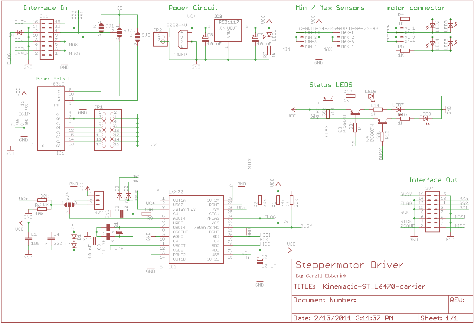
So I designed a schematic [2] and a PCB [3] to make use of the full capabilities of this small chip.
One of these problems was that the speed of production was limited by the fact that the controller was not capable of controlling the steppermotors at the speeds that the mechanics allow for.
During the design process I ran into several problems. As Eagle CAD was the defacto standard in the RepRap community it met me with some nice challenges:
- I like to put different functionality on different sheets in the schematic, being limitied to only one I had to cram a lot into a single A4, which means that it does not look as tidy as I would have liked.
- The device, package and symbol of the L6470 did not exist. So I created them and updated the RepRap Eagle library [4].
- During this proces I found that Eagle cannot deal with Exposed-PADS. To circumvent this I drew a stop polygon in its place and then use a polygon during the PCB layout to fill it with the appropiate (GND) signal
- The autorouter isn’t capable of the complexities in the board. So I had to route all the signals by hand. A Design Rule Check (DRC) with the capabilities of The PCB Shop comes up with no errors.
Now that I’ve designed a first version of the PCB I would like to ask for your comments (it’s an RFC!).
As any engineer knows, nobody is perfect. So I will have some things I did not see, or have done some thinking which is not straight. This means that I would like to have as much feedback as I can possibly can have.
One source of this feedback is this blog.
Critisim and ideas I already have myself:
1. From the center the top-left part is pretty empty, the board could be more compact.
2. Get rid of the daisy chaining capabilities, this would get rid of a connector and the jumper array, make the other connector more compact and would get rid of the multiplexing electronics. probably shrinking the board size
quite considerably.
3. Erik proposed to use a “PCI card style” board edge connector, this has not been implemented.
[1] www.st.com/internet/analog/product/248592.jsp?wt.mc_id=enews_jan11_dspin
[2] www.reprap.org/wiki/File:GE_stepper_version_0.8b.sch
[3] www.reprap.org/wiki/File:GE_stepper_version_0.8b.brd
[4] www.reprap.org/wiki/File:Reprap.lbr#file
Hey Gerald, nice to see (read) you here too!
Hi,
Great post.
One suggestion – lot of reprap electronics work on 5V and you connected Vref and Vdd to a same rail. Vref needs to be on 3V – 3V3 and will be using it’s internal regulator of power is not provided to it, but if you want to use 5V ttl then you have to bring 5V to Vdd. This is why I think you might want to keep Vref and Vdd on separate rails or leave Vref with a cap only so it can supply internal logic with internal regulator and you leave Vdd to be brought from “outside” so user can select to use 5V or 3V ttl .. REG1117 can be any voltage you want so It is not clear that you want to use 3V3 one there (as if you use 5V one there it will kill the L6470).
Wrt chaining the devices, good idea but I’d then prefer to have external oscillator and to use that same oscillator to drive all chained devices; so all oscin pins on all chained devices need to be linked together and on the pcb there should be place to populate (or ignore) external oscillator circuit, either a 4pin oscillator or an xtal + caps + some inverter ..
hope it makes sense 😀
all best
b.
Bogdan,
That is the problem with organic designing. It grew this way. Originaly I didn’t implement an external regulator at all, but then added some more electronics, found that I went over the 40 mA the L6470 provides and added it.
I’ll take your comment and will implement it in the next version.
Looks like an excellent chip, however I do have one concern- the main reason we have step pins running to one controller is so that all the motors remain synchronized to each other and the intended move. With this level of abstraction, how do you prevent geometric errors, eg X finishing before Y, and how do we implement acceleration without geometric errors?
On closer reading of the datasheet, it does have an external step input mode, direction still needs to be set via SPI which works great for our purposes, we do skip a lot of the tastier logic in the chip though
For this reason the Step-clock signal is also provided on the interface.
Hi Gerald,
Interesting choice of L6470. I’d like to suggest you to take a look carefully at Pololu A4983 Stepper Motor Driver Carrier pcb. Fat and short motor power in/out lines, 4 small through holes each for penetrating layers are key for success. Your 45 degree corner lines are nice but do not try to pass between C2 pads. Good luck!
Cheers,
Genie
We intend to enhance the PCB thermally. We’re thinking of:
* more copper weight
* 4 layered board instead of 2.
* a grid of thermal via’s beneath the chip (0.25 mm size)
BTW: As far as I understood it, this chip generates much less heat than the Allegro chip on the Pololu. It has a lower Rds(on).
Great! Looking for progress…
Genie
Is this blocking the release of Ultimaker? Would be nice to have some kind of status update. I’m really thinking of preordering one even though I’m building myself a prusa mendel 🙂
No, we will not wait for these drivers to be developed! We have a very nice Arduino Mega + Pololu setup with good results. Pololu’s availability is not great, but we’re also working on an alternative supply for this.
Hi Gerald,
Great work.
I would also get rid of the daisy, this will make the board considerably smaller.
PCI style would be realy great.
Most of the endstops work on a NC contact to 5V, so that part would have to be checked for compatibility.
An other idea is to have 2 output connectors for 2 motors for prusa-style Z-axis
My main concern lies in the availability of the chip itself.
Both RS and Farnell do not have it in their program, and that means you would have to have a direct connection to STM to not have bigger supply problems than pololu has at the moment.
Currently Digikey does stock the L6470. But since it is rather new I expect RS and Farnell to pick it up soon (they are not the fastest and often only put things online after they have been ordered a few times). Maybe I will give them a call later this week.
This chip is a nice find.
I’m not sure I understand the use of complex multiplexing tho. Why not use the normal SPI daisy chain? It took me a fair bit of googling to figure out how, since the datasheet only alludes to it.
I’m seeing it kinda like this: the motherboard has spots for x of these boards vertically oriented. The SDO of one going to the SDI of the next. The last one will have SDO going to the uC. If not all of the positions are populated, you put in a terminator that send SDI fir that position to the uC.
Software-wise, as I understand it, you should be able to write a 0x01 then keep clocking in 0x00 until the 0x01 comes back in. Count the number of clocked bytes to see how many are populated.
This also solves syncing issues, you clock in commands to all of them at once, them when you flip CS they all start moving. I’m not sure about the use of sync/busy at this point yet, however. I’d assume this is only of use to the uC, but not for syncing between drivers…
Combining the alarm from all drivers gives a great interrupt source.
As for pci style connectors, why not just put a .1″ strip of right-angle male header along one side, and use that to mount vertically? A quick search proves that the pci-style board connectors are much more expensive than simple headers, even counting having to buy both sides. (Not to mention added expense of gold-tipped fingers on the PCB. And an odd part to become hard to find…)
If I get a chance I’ll put some of these ideas in eagle.
-Rob
Rob, those are good points. 90 degree headers sound better. Besides, female headers as outputs (when some of them are power outputs) would be safer to use.
The eagle files are available for this board, so don’t hesitate to hack those. That is the whole point of publishing them.
Also, note that ST provides free samples (two of each chip).
Actually in the new revision that is the case, I use 90 degree headers. For routing it is hell but for usage it is okay.
There are surface mounted headers which have the metal sticking in alternating directions. Maybe that’s a good option to make routing easier? I also discovered that through-hole is a pain to route.
Gerald: is that in the file linked to in the article?
I’m going a slightly different direction, I think. I’m aiming for a simple carrier board (similar in concept to many of Pololu’s) with a simple interface. All of the major parts will have to be on the “parent” board: power, endstop connectors, stepper connectors, etc.
Also, since I can’t find a way to do it with software I’m using a SPI digital pot to set the power. That combined with the missed-step alarm and autotuning the steppers is likely possible.
Once I have a design to show, what would be the preferred method of sharing?
Rob: No currently I have only the schematic finished [1,2] in KiCad. I moved away from Eagle, because of the limitations in the number of layers.
It is a little different from your idea, the connectors are on the daughterboard (since you cannot use them without it). The power etc is expected from the motherboard (although motor power can be supplied, this because of possible interference the PWM signals might have in the input power).
Routing is a little harder to do in KiCad, since I want to do “necking” on my traces.
I have not thought about a way of sharing. Since all KiCad file are plain text I would expect something like GIT to be a nice way to share. Now to just find a way to setup up a repository somewhere.
[1]http://dl.dropbox.com/u/21215791/KineMagic%20Small.pdf
[2]http://dl.dropbox.com/u/21215791/KineMagic%20Small-Interfaces.pdf
Dear all,
I have updated our blog to some new software in such a way that it is now usable (alas nog spam protection in place waiting for the provider to change the security settings)Also I have some other topics to blag on. Like: Our children, Sjoe
The schematic block for the L6470
For the people that did not read my guest blog on Erik his page.I have been involved in designing some new electronics for the reprap project. This means that I have added a new category for my own blog. Th
The Pololu A4983 and A4988 boards appears to be a copies of Allegro’s reference PCB design. It’s main advantages are low cost and rectangular pin connectors. The Reprap wiki rates it a 1 Amp usable due to heat issues.
I would suggest MTA-100 series connectors for the motor, limit switch(es) and motor power supply (i.e TE Connectivity CONN HEADER VERT 4POS .100 TIN 640456-4) due to low cost and 5 Amp rating.
A 4 layer PCB is 2.5 times more expensive than a 2 layer one. The number of vias and PCB area are big factors (see Ti app note slma002g).
One of the previous comments was the availability of a step clock to synchronize the other axises. I would suggest looking at USB 2.0 via an atmega32U2 using micro USB connector to get high speed shielded cabling at low cost.
This micro could also implement a higher level of interface commands.
There a lot of software to be created using this design.
Murray