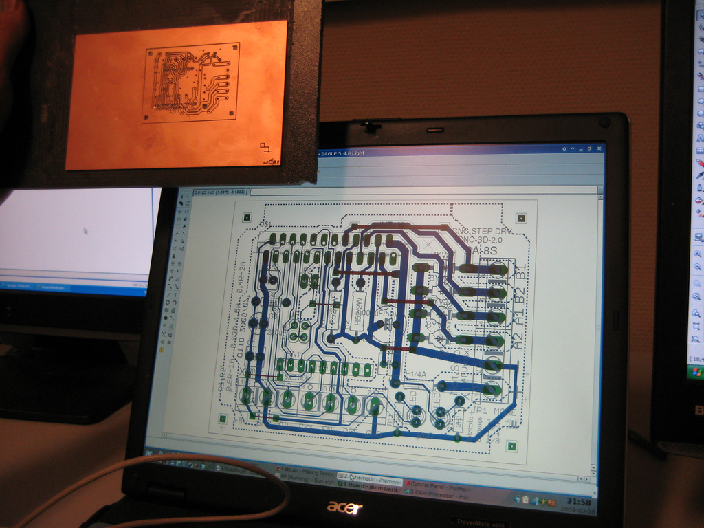
Building a microstepping precision motor driver
Two weeks ago I made print circuit board for a more advanced stepper motor driver, using the IMT-901. This is a chip that can drive power to the motor and control motion in a very precise way (micro stepping). It can in theory increase the precision of the machine from 0.125 mm to 0.0078 mm, or 7.8 micrometer. Of course the accuracy in practice is not in that range, but it will probably allow smoother motion and better detail of small features.
I use the following files:
http://reprap.erikdebruijn.nl/files/imt901.zip
It can be opened in Eagle (>= 4.2, I guess)
This guide explains the steps I took: http://fablab.marcboon.com/pcb/
A possible problem with the PCB might be that C4 (1000uF) is pretty close to R2, if R2 gets hot (not just warm, I mean hot), it can damage C4 in time (thanks for pointing this out, José!).
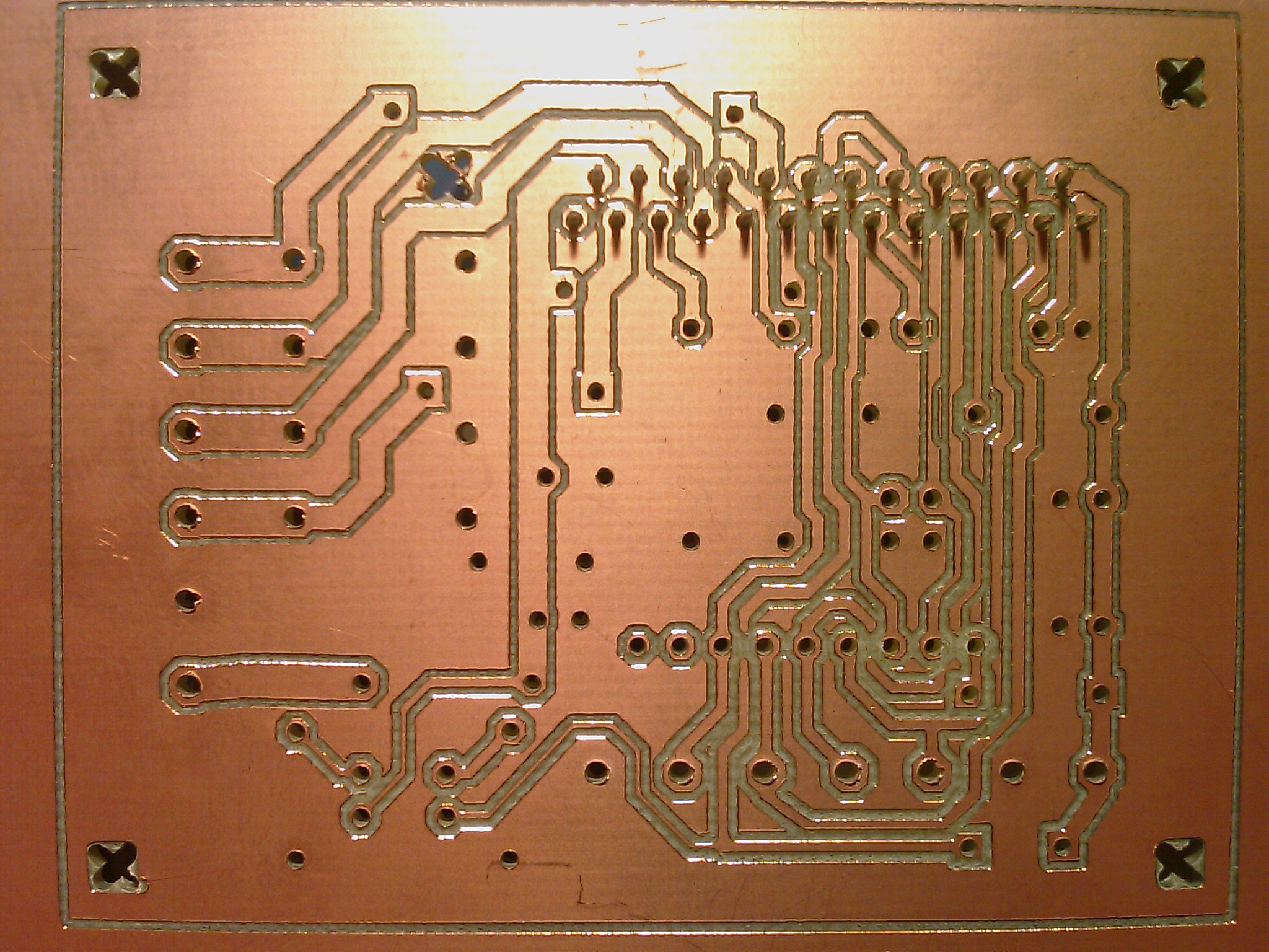
I like the IMT chip because it includes the logic an drives the power for the stepper, microstepping included. This board layout was nice because it can be made with single side copper (with just a few bridges needed).
Microstepping could improve precision and remove a lot of vibration in the frame (loosening screws and noise). I hope it will make a difference!
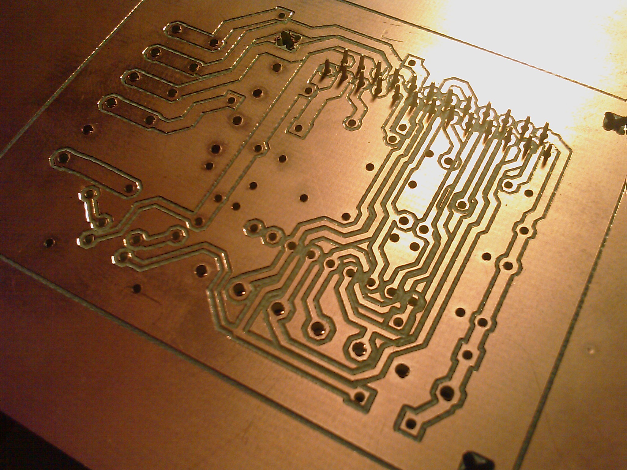
Here are some screenshots of milling the PCB:
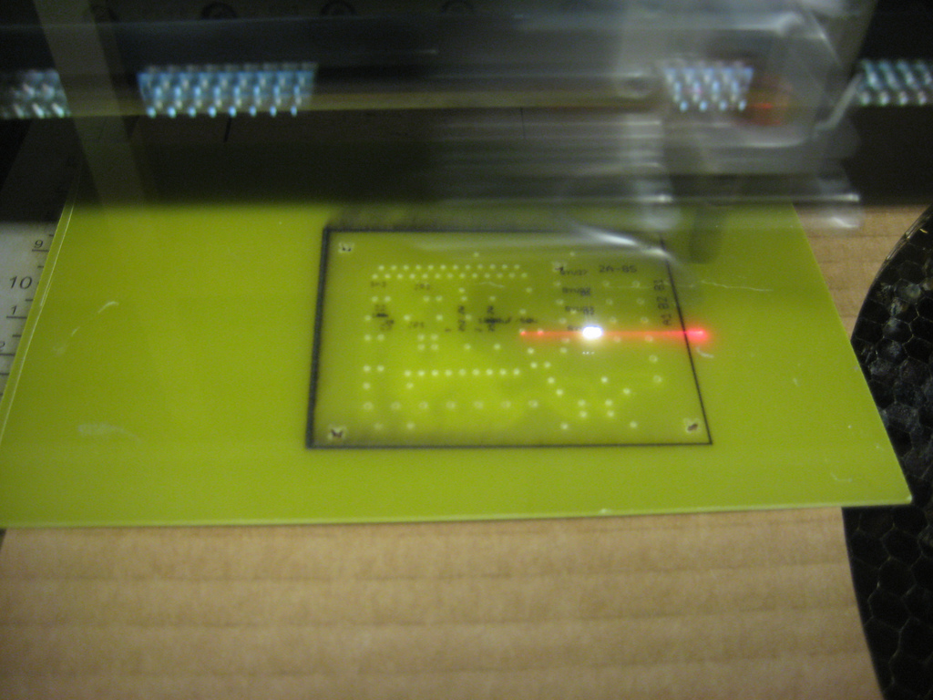
This is a good site that explains making g-code to do milling (so you can do it on a RepRap):
http://www.brusselsprout.org/PCB-Routing/
Perhaps I’ll be working on it some more this evening!
Hi Erik,
Did you mill that on your Darwin, or something at FabLab?
Chris
I did this one on the Modela in the FabLab.
Good question, because it could have been on the RepRap:
http://blog.erikdebruijn.nl/archives/62-RepRap-in-simple-terms,-part-1-replication..html
Yet I don’t have any working Atmega664P’s anymore, so my printer’s down again. Programming them with my LPT port programmer doesn’t work anymore.